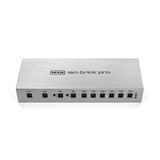
A pedalboard becomes much easier to use when its power system is planned as carefully as its signal chain. The relevant questions are practical: will every pedal start reliably, are the plugs compatible, can the supply fit beneath the board, and can a problem be traced without dismantling the whole setup? A larger number printed on a power supply does not answer all of them. Voltage, current capacity, polarity, connector dimensions and the relationship between outputs are separate specifications. This guide explains how to read them and build a sensible connection plan, using the MXR Mini Iso-Brick M239, Iso-Brick M238 and Iso-Brick Pro M242 as concrete examples. The discussion is based on manufacturer documentation rather than a claim that we personally tested every possible combination. Always check the instructions for the exact revision of each pedal you intend to power.

1. Start with a complete pedal inventory
Before shopping, put every pedal on the table and record its exact model designation. A familiar product name can conceal different generations with different electrical requirements. For each unit, note the required supply voltage, whether it needs DC or AC, connector polarity, connector size and the manufacturer's stated current requirement. Include pedals that are used occasionally, such as a looper brought out for practice or a digital delay added for particular songs. Record where each specification came from: a label, the current manual or a manufacturer support response. This small inventory prevents a common planning error: counting six pedals and assuming that any six-output supply will work. Six modest analogue effects and six demanding digital devices can require quite different arrangements. If a specification is missing or ambiguous, resolve that individual question before assigning the pedal to an output. A guess is not a useful entry in a wiring plan.
2. Match the voltage before considering anything else
Voltage is a requirement, not a measure of how premium a power supply is. A pedal specified for 9 V should receive the voltage its manufacturer permits. Do not connect it to 18 V merely because another pedal of the same general type accepts that voltage. Some effects explicitly support a range of supply voltages, but that permission belongs to that exact model. It cannot be transferred to every overdrive, compressor or preamp. On a supply with adjustable outputs, check the switch or control before inserting the pedal cable. Mark outputs that are intentionally set above 9 V so that a hurried rearrangement does not put a different pedal on the same lead. When comparing products, separate fixed-voltage outputs from selectable or continuously adjustable ones. They offer different kinds of flexibility, and none should be treated as an automatic voltage detector unless the manufacturer expressly describes that function.
3. Distinguish AC input from DC pedal output
An adapter can take AC from the wall and provide DC to a pedal or distribution unit. Consequently, the presence of an AC rating on its label does not mean that its low-voltage output supplies AC. Read the input and output lines separately. Some pedals genuinely require an AC supply; a conventional DC pedal output is not a substitute just because the connector fits and the voltage number looks familiar. Equally, an AC output should not be connected to a DC-only pedal. When a device uses a dedicated manufacturer adapter, keeping that adapter can be the simplest correct solution. A tidy board does not justify forcing every device onto a single incompatible supply. If the technical description is unclear, compare the pedal manual with the power supply manual directly. Shopping filters and abbreviated product titles rarely contain enough information to settle an unusual AC-versus-DC requirement by themselves.
4. Read the polarity symbol carefully
Many guitar pedals use centre-negative DC connections, but this is a common arrangement rather than a universal rule. The polarity diagram identifies which conductor connects to the central pin and which connects to the surrounding barrel. Check the symbol on the pedal and the output or approved cable arrangement. Do not infer polarity from the colour of a plug, the brand of the pedal or the fact that a cable was found in the same drawer. A polarity-reversing cable changes a specific electrical relationship; it should only be used when that change is actually required. Vintage-style circuits described as positive ground introduce another consideration that is not resolved simply by looking at the outside of a plug. Follow the pedal manufacturer's power instructions and isolation requirements. If those instructions call for a separate isolated source, treat that as part of compatibility rather than an optional way to reduce noise.
5. Understand what the current rating means
Current capacity is different from voltage. With the correct voltage, polarity and connector, a regulated output rated for more current than a pedal requires can normally power that pedal: the rating expresses available capacity rather than a command to force the maximum current through the device. For example, a hypothetical pedal requiring 100 mA can be assigned to a compatible 300 mA output. The reverse assignment is not supported merely because the pedal appears to light up. Insufficient current may cause unreliable startup or operation. Use the pedal manufacturer's specified requirement rather than an estimate based on its physical size. A compact digital effect can be more demanding than a larger analogue unit. Also distinguish a supplied adapter's maximum capacity from the pedal's documented consumption. An adapter label alone does not necessarily state the exact amount drawn by the pedal in normal use or during startup.

6. Check individual outputs and the total budget
A power supply can impose both a limit for each output and a limit for the complete unit. Passing one check does not automatically pass the other. Build the connection plan around both specifications, especially when selectable outputs are used at higher voltages. Power in watts is voltage multiplied by current in amperes, so the same current at 18 V represents twice the power of that current at 9 V. This relationship is useful for understanding a budget, but it does not override the manufacturer's stated operating limits. Do not simply add every output's largest printed number and assume all outputs can provide those maxima simultaneously. Where a manual describes total output power, expansion limits or a particular allocation rule, follow that information. If a specification table appears inconsistent, ask the manufacturer about the intended combination rather than publishing a confident capacity calculation based on an uncertain assumption.
7. A matching-looking plug is not enough
Barrel connectors have more than one relevant dimension. The outside diameter, inside diameter and effective insertion length can all matter. A plug that enters a socket may still be the wrong fit, and intermittent contact is particularly troublesome on a board that is moved between rehearsals. Check the connector specification for both ends of the cable. Right-angle plugs can reduce the space needed beside a pedal, but they may collide with adjacent audio jacks or prevent two neighbouring sockets from being used together. Straight plugs can solve that problem while creating a different clearance issue at the edge of the board. Choose the cable after looking at the actual socket arrangement. Avoid treating an assortment of adapters as a universal compatibility kit. An adapter changes only the properties for which it is designed; it does not automatically correct voltage, current capacity, polarity and connector dimensions at the same time.

8. What isolated outputs can and cannot do
Isolated outputs provide separate electrical supply sections according to the unit's design. This can help keep pedals from interacting through shared power connections and can address certain noise problems in mixed pedalboards. However, multiple sockets do not by themselves prove that every socket is independently isolated. Some supplies use groups of outputs, so read the manufacturer's description rather than judging the enclosure. Isolation also does not promise a silent rig under every circumstance. Noise can enter through pickups, audio wiring, gain stages, USB connections or other equipment. A noisy cable or an overloaded input remains a problem even with excellent power distribution. Think of isolation as one useful property within a complete system. It is particularly valuable when planning separate supplies for devices that should not share a common power connection, but it is not a replacement for checking each pedal's basic electrical requirements.
9. When a daisy chain is a reasonable choice
A daisy chain distributes one compatible supply connection to several pedals. The connected pedals must share the required voltage and polarity, and their combined current requirement must fit within the available output capacity. Three hypothetical pedals requiring 50 mA each represent 150 mA before any additional planning margin or manufacturer-specific requirement is considered. They also share that power connection; adding several plugs does not create independently isolated outputs. For a small group of compatible low-current effects, this may be a practical arrangement. For a more complicated board, especially one mixing devices with different requirements, individual outputs can make both planning and fault-finding clearer. Test the intended combination rather than assuming that a chain will always be noisy or always work perfectly. Keep a record of which pedals share an output, because adding one more effect later changes the current calculation for the entire group.
10. Do not confuse different kinds of Y cable
Two cables with similar branching shapes can perform very different jobs. A splitter distributes one output to multiple devices. A manufacturer-approved current-combining arrangement can use compatible outputs in a specified way to increase available current. A voltage-combining cable can connect appropriate isolated sources in series to produce a higher voltage. These functions are not interchangeable, and using the wrong cable can produce an unsuitable supply at the pedal. Read the exact accessory description and the power unit's compatibility instructions before buying. A series connection that adds voltage does not also add current capacity in the same way. Do not improvise combinations merely because two connectors are available. If a demanding pedal cannot be assigned to a suitable native output, an approved solution documented for that equipment is preferable to an experiment with unidentified cables. Label specialist cables so that they are not later mistaken for ordinary power leads.
11. MXR Mini Iso-Brick M239: plan around five outputs
The MXR Mini Iso-Brick M239 illustrates why output types matter more than a simple socket count. Its documented arrangement provides four 9 V outputs rated at 300 mA and one selectable 9 V or 18 V output rated at 800 mA. That makes the selectable socket a distinct planning resource, not just another interchangeable connection. If it powers a pedal at 18 V, it cannot simultaneously serve as a separate 9 V output for another effect. Check the overall operating limits in the current manual as well as each individual rating. The unit itself receives power from its supplied external adapter, so its installation includes both the compact distribution box and the adapter's practical placement. In the SoundsGood catalogue, this model is identified by SKU 36813. Use the exact model designation when checking the supplied accessories, because similarly named power products can have different output arrangements.

12. MXR Iso-Brick M238: several output groups
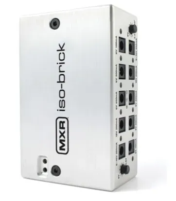
The full-size MXR Iso-Brick M238 provides ten isolated outputs arranged in different groups. The manual lists two 9 V outputs at 100 mA, two at 300 mA, two at 450 mA, two 18 V outputs at 250 mA and two variable 6–15 V outputs at 250 mA. These are useful distinctions when allocating pedals: a fixed 18 V socket is not spare capacity for an ordinary 9 V-only device. Likewise, the adjustable outputs require deliberate settings and compatible pedals. Start the wiring plan by allocating any unusual voltage requirements, then place the remaining pedals on appropriate fixed outputs. Check the complete supply limits rather than treating every printed maximum as an unconditional simultaneous allowance. The catalogue SKU is 32857. The model uses an external supply, so remember to include that component when assessing the space, transport arrangement and power connection for the finished board.

13. MXR Iso-Brick Pro M242: consider the complete allocation
The Iso-Brick Pro M242 adds a different set of options. Its manual lists four 9 V 300 mA outputs, two 9 V 500 mA outputs, two selectable 9/12/18 V 500 mA outputs and a 9 V 1.5 A output intended for demanding multi-effects applications. A separate 18 V 2 A LINK connection serves compatible expansion; it should not be treated as an ordinary 9 V pedal outlet. The stated maximum total output power is 42 W, so the individual socket ratings still need to be considered within the complete budget. An appropriate current rating does not settle connector compatibility: check the precise cable required for the particular multi-effects device. In the catalogue, look for SKU 41177. This model may suit a different board layout from the smaller units, but the sensible choice depends on the actual pedal inventory, mounting space and expansion plan rather than the word Pro alone.

14. Keep the supply input separate from its outputs
The connector that powers a distribution unit is not necessarily an output available to a pedal. On the M238 and M239, the specified external adapter supplies the unit through its input connection. Its rating must not be read as permission to apply that voltage to every effect on the board. The M242 instead has a mains input arrangement described in its manual. Study the labels before routing cables, particularly when a compact enclosure places several similar-looking connections close together. Keep mains and low-voltage connections easy to identify during setup. Use the appropriate supplied or manufacturer-approved input lead and adapter. If equipment is moved between countries, confirm the input voltage range and the correct regional mains lead rather than relying on a plug converter alone. All these checks concern the source feeding the power unit; the voltage delivered to each pedal remains a separate output specification.
15. Build a realistic connection map
Imagine a board containing a tuner, overdrive, chorus, digital delay and reverb. The names of those effect categories are not enough to assign outputs. First fill in the exact requirements for the five actual models. Then reserve any high-current or unusual-voltage connections, allocate the remaining devices and confirm the total budget. Draw a simple map showing the supply socket, cable type and destination pedal. If a daisy chain is used, show every device on that branch and its combined requirement. Include the physical route, because a technically correct assignment may need a different cable length once the board is assembled. Store the map with the equipment or keep a clear photograph on your phone. During a rehearsal, being able to identify one cable quickly is more useful than trying to remember which identical black lead was intended for the delay several months earlier.
16. Treat analogue and digital pedals as individual devices
Analogue and digital are useful descriptions of broad design approaches, but they are not complete power specifications. Do not assume every analogue pedal can share one output or every digital pedal requires the largest available socket. Read each device's requirements. When checking a mixed board for noise, add one pedal at a time and keep the amplifier settings consistent. This makes it easier to identify a change associated with a particular connection. If a problem appears only when two devices share a supply branch, test them on suitable separate outputs before changing unrelated parts of the rig. Also consider audio level, gain and cable routing: an apparent power issue may originate elsewhere. A disciplined sequence produces more useful information than replacing several cables, changing the pedal order and moving power connections simultaneously. Record a configuration that works so it can be restored after an experiment.
17. Check mounting space and ventilation
Measure the real installation space, including connectors and the bend needed in their cables. The enclosure dimensions alone do not show whether a supply will fit beneath a particular board. Check the height above the floor, clearance around mounting brackets and whether a cable will be pinched when the board is placed in its case. Keep ventilation openings unobstructed and follow the manufacturer's mounting guidance. A convenient position should also allow access to voltage selectors and labels without dismantling the entire rig. Secure the unit with a suitable mounting method rather than leaving it to hang from the power leads. If drilling or modifying a board is necessary, protect the equipment from metal debris and use an appropriate competent installer where needed. After mounting, inspect the system in the transport case as well as on the floor: pressure from the case lid can reveal a problem that is invisible during normal use.

18. Choose cables for serviceability
The shortest possible cable is not always the most practical one. Allow enough slack to remove a pedal for inspection without pulling on its socket, while avoiding large loops that catch on nearby equipment. Route leads so that footswitches, expression pedals and moving mechanisms cannot crush them. Identify cables carrying unusual voltages and any specialist adapter leads. A small label can prevent an expensive reconnection mistake when several pedals are removed for cleaning. Keep spare leads of the actual connector type used on the board instead of a random assortment that only looks similar. Inspect damaged insulation, loose plugs and intermittent connections before a performance. When packing the board, check that the case does not force a plug sideways. Good cable organisation is not just cosmetic: it makes an electrical problem easier to isolate and reduces the temptation to reconnect an unfamiliar lead in a hurry.

19. Commission the board one device at a time
Before the first complete startup, compare the physical wiring with the written map. Confirm voltage settings, polarity, connector fit and current allocation with the system unpowered. Start with one compatible pedal, check that it boots and passes signal, then build the arrangement gradually. A lit indicator is useful evidence, but it does not prove that every operating function is stable. For digital effects, allow the normal startup process to finish and check the modes you actually use. Once the full board is working, power it down and restart it as a complete system. A setup that only succeeds when connected in a particular improvised sequence deserves further investigation. Keep listening levels moderate while testing so that unexpected switching noise is manageable. Finally, verify that the board still works after it has been placed in its case and transported normally, since loose connections may appear only after movement.
20. Diagnose a pedal that will not start
If a pedal does not power up, disconnect it and revisit the basic specification rather than increasing the voltage. Check that the selected output is appropriate, the cable is fully inserted and the source itself has power. Try a known compatible lead if available. Compare the pedal's stated current requirement with the output capacity, including any other devices sharing that connection. If the pedal works with its approved original adapter, that comparison can help narrow the issue to the board's supply arrangement or cable compatibility. Do not treat repeated resets or partial startup as acceptable operation. Stop using a connection that produces unusual heat, smell or visible damage and have the equipment assessed. The aim is to identify one failed assumption at a time. Randomly moving the device between sockets of different voltages makes the diagnosis less reliable and can introduce a problem that did not previously exist.
21. Investigate hum without removing protective earth
Hum and digital noise need a systematic listening test. Establish a simple guitar-to-amplifier reference, then add the board and its connections in stages. Note whether the noise changes when a particular pedal, audio cable, USB connection or external device is introduced. Use appropriate isolated outputs where required, but do not assume that power isolation will resolve every source of interference. If a computer connection creates a problem, examine the audio and USB arrangement within the equipment manufacturers' recommendations. Never remove a mains protective-earth connection as an improvised noise cure. Protective earth serves a safety function that is separate from the convenience of a quieter signal. For a difficult system-level problem, involve a qualified technician familiar with audio equipment. A documented sequence of observations helps that technician far more than a general statement that the board is noisy under circumstances that cannot be reproduced.
22. Use variable voltage only when the pedal permits it
Some players explore reduced voltage, often described as sag, with specific compatible effects. This is not a universal tone control for every pedal. A digital device may fail to operate correctly at an unsuitable voltage, while another circuit may have different restrictions. Check the exact pedal manufacturer's guidance before using a variable output for this purpose. On the M238, the presence of adjustable outputs supplies a capability; it does not establish that every connected pedal supports the full adjustment range. Label an intentional setting and keep it separate from ordinary fixed-voltage connections. If a sound experiment is permitted, make controlled changes and note the original configuration. Do not use an unfamiliar live setup as the first test. Reliable operation should be established before a rehearsal or performance, and any unusual power arrangement should remain understandable to someone helping reconnect the board later.
23. USB power banks require a complete compatible system
A USB power bank does not automatically become a suitable guitar pedal supply when a barrel cable is attached. The required voltage, conversion method, current capacity, polarity and connector still need to be correct. Some arrangements rely on a specifically designed converter or a supported power-delivery mode; that functionality must be documented rather than assumed. Check the complete combination of power bank, converter and pedal, including whether the bank remains active at the actual load. Runtime depends on conversion losses and operating conditions as well as the capacity printed on the battery pack. A realistic rehearsal test is more informative than a confident runtime promise derived from one headline number. For mobile playing, also plan how the battery will be secured and recharged. A portable arrangement is useful only if it remains stable when cables move and can complete the intended session with an appropriate practical reserve.
24. Prepare for transport and quick setup
A board that works at home should also be easy to reconnect in a different room. Keep the input power lead, approved external adapter where applicable, and any unusual connector accessories together with the board. Carry a small set of compatible spare low-voltage cables. Photograph the output assignments and make labels legible under ordinary stage lighting. Before travelling, check that adjustable voltage settings have not been moved accidentally and that no plug bears pressure from the case. At the destination, inspect the mains connection and use equipment appropriate to that location. Avoid placing the supply where drinks can spill onto it or where another musician will step on its cables. Build a short setup routine that checks signal and essential effects before performance volume is raised. Consistency reduces the number of last-minute changes and makes it easier to recognise when something differs from the configuration that was already tested.
25. Reserve capacity for a plausible future board
Expansion planning is most useful when it is specific. If you expect to add a demanding digital multi-effect, reserve a compatible output and connector solution for that type of requirement. If the likely addition is a modest analogue effect, the priorities may be different. Extra sockets with the wrong voltage or insufficient current are not meaningful spare capacity. Consider the total budget, physical mounting room and cable access as well as output count. An expansion connection such as the M242 LINK should be used according to its documented purpose and compatible equipment. It is not a general invitation to connect any device that accepts a similar plug. A smaller supply that fits the current board accurately can be a better practical choice than a larger unit whose features are not needed, while a clearly planned future setup may justify buying additional capability now.

26. Check the package before ordering
Compare the exact model, included adapter or mains lead, low-voltage cable selection and any mounting accessories with the intended installation. Do not assume that every cable shown in an unrelated review is included in every regional package. Confirm warranty and service arrangements through the seller's current information, and ask about any accessory needed for a nonstandard pedal connector. Keep the manufacturer manual with the connection plan. For the three MXR examples in this guide, use the model codes M239, M238 and M242 together with the catalogue identifiers to avoid confusing related products. A useful purchase conversation includes the pedal inventory and the proposed output assignments. That gives the seller or manufacturer a concrete compatibility question to answer. It is more reliable than asking whether a supply is powerful enough for a board without specifying what the board actually contains.
27. A practical order for making the final choice
Choose in a fixed sequence: document every pedal's requirements, identify compatible output types, check individual and total capacity, confirm the cable arrangement, then assess mounting and transport. Only after these steps compare convenience features and appearance. The Mini Iso-Brick, Iso-Brick and Iso-Brick Pro demonstrate three different allocations of outputs rather than a simple universal ranking from small to large. The right unit is the one that supports the intended connections within its documented limits and remains easy to use. Once installed, verify startup, signal and noise in the actual rig, record the working configuration and keep suitable spares. This approach turns power distribution into a predictable part of the instrument setup. Instead of guessing whether an available socket will do, you will know which pedal belongs there, why the connection is compatible and how to trace a problem if the board changes later.