Define the route through the insert
Before choosing a cable, find the insert description in the mixer or other device's documentation. Establish its position in the signal path, connector arrangement and send and return functions. This determines which channel will pass through the external compressor, equaliser or other processor. A cable name without an equipment diagram cannot reliably establish suitability for the job. Start with the port documentation and then choose the assembly.
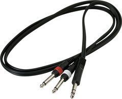
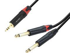
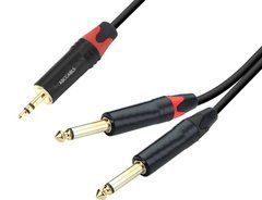
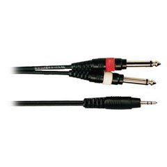
The Yamaha explanation of inserts describes a common one-TRS-to-two-TS arrangement, with one branch going to the processor and the other returning. It also recommends checking tip and ring functions on the actual mixer because assignments can differ.
Describe the route in words: the selected channel's insert, processor input, processor output and return. Add equipment models and photographs of the relevant sockets. This short description helps distinguish serial processing from a stereo breakout or an ordinary connection between two devices. For multiple channels, create separate entries so the cable count follows the real system.
A TRS lead is not automatically an insert breakout
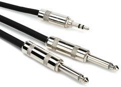
TRS describes the contacts on a plug. It does not establish how many ends the assembly has or where every contact connects. For example, the manufacturer presents the MXR 3 FT TRS Stereo Patch Cable with one angled and one straight end. It should not automatically be treated as a Y cable for separate processor input and output sockets.
Check the exact part number, connector count, types and wiring. If the photograph shows two ends while the application needs three, confirm the contents before purchase. Some equipment also implements inserts differently, so a universal rule based on appearance is unreliable. Select the cable around a documented route. Adapting an already purchased assembly with miscellaneous couplers adds connection points and makes later testing harder. Establishing the required construction first is more practical.
Send/return labels and breakout reach
Once wiring is confirmed, identify the branches by send and return function. Colour is a useful aid but should not be guessed. Plug labels may say tip and ring while the diagram uses function names; retain the correspondence. Add channel numbers when several processors are installed, since repeated send/return labels will not distinguish neighbouring pairs. The markings should be readable with the cables in their normal working positions.
Measure the total mixer-to-rack distance and the separation required between the two branches. Processor input and output sockets can be far apart or have different access. Adequate overall length will not help if the breakout itself is too short. Avoid tension between ports and allow one end to be disconnected for testing. For angled housings, check cable direction and neighbouring connector clearance, particularly in a densely populated rack. Service access should be part of the initial choice.
Operating levels and processing checks
The cable does not automatically match levels between equipment. Confirm the processor's input and output modes and the mixer's insert requirements. If several sensitivity settings are available, select them using the manuals and watch the meters. Do not try to correct overload by changing cables at random or making a large adjustment to one control without identifying the cause. Establish a compatible operating mode for both devices first.
After connection, compare processing with the intended bypass mode. Test one channel and one processor so the result remains understandable. For vocal compression, confirm the route before adjusting compressor settings. Save the working levels for the next setup. With a stereo processor, establish both channel connections separately: one mono insert lead does not define the entire stereo arrangement. When another operator will use the system, provide the routing diagram and selected modes as well as the cable list.
If the signal disappears after connection
First check the complete path through the processor: correct input and output, power and intended operating mode. Compare branch labels with the wiring diagram. Avoid moving every cable at once, which makes the cause harder to identify. If the original route without external processing worked, compare it with the new arrangement using the device instructions and test the added elements in sequence. Keep specific notes when investigating a recurring problem.
Control system volume before switching connections. Do not treat a partially inserted plug as a universal working method; special socket behaviour must be explicitly documented by the manufacturer. A tested spare cable with the same wiring helps separate a contact fault from an incorrect setting. Label a damaged assembly and remove it until repaired. Afterwards, check each branch and the complete route with the actual equipment. The full connection test establishes whether the lead is ready to return to the working kit.
Questions before ordering an insert cable
Is the description stereo cable enough? No. You need the number of ends, connector types, wiring and equipment requirements. Stereo may describe a different application from the send and return of one channel. Confirm those details before ordering.
Can any effects pedal be connected? First check level compatibility, inputs, outputs and the pedal's intended application. An insert cable does not turn a studio route into an instrument connection or provide the required interfacing by itself.
How should rack length be chosen? Measure the route to the mixer's working position and separation between processor ports. Include breakout reach, rear rack space and servicing allowance. Large unnecessary loops make a particular pair harder to locate among other leads.
What helps with accurate selection? Provide mixer and processor models, the manual's insert diagram, distances and panel photographs. If a different TRS function is required, identify it separately so the selected assembly matches the actual task.
SoundsGood supplies sound equipment for educational institutions, studios, concert halls, conference rooms, and public and private organisations. A technical brief can be used to agree on system components, specifications, a commercial quotation, documentation and delivery arrangements.